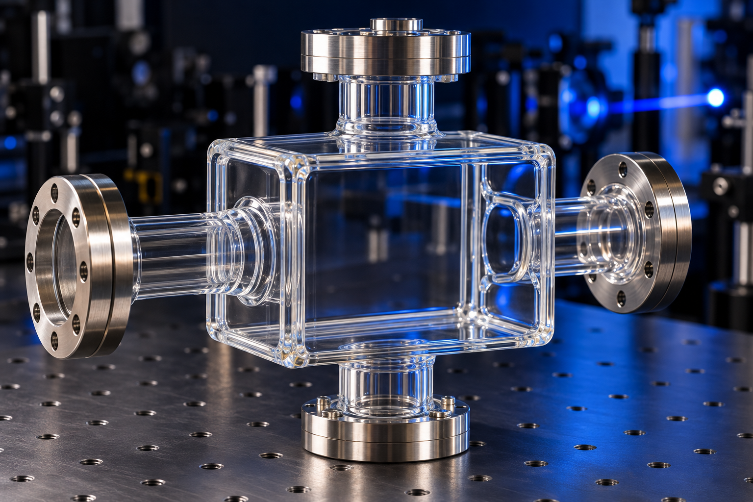
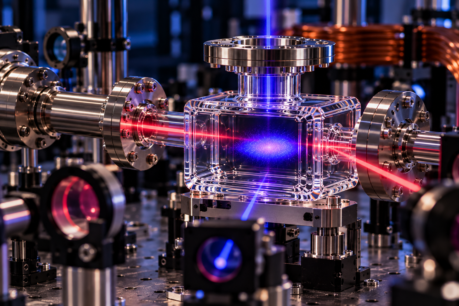
Catching Atoms With Light: Inside the Magneto-Optical Trap (MOT) Cell

you’re as cold as ice!

If your experiment involves slowing atoms down to a crawl, trapping them with light and magnetic fields, and studying what happens when matter gets really cold, there is a good chance a Magneto-Optical Trap (MOT) Cell is somewhere in the setup.

Magneto-optical traps have become an important tool in atomic, molecular, and optical physics. By combining carefully tuned laser light with a spatially varying magnetic field, a MOT can cool and confine neutral atoms, in some cases reaching temperatures in the microkelvin range.

But lasers and magnets are only part of the equation.

Those atoms need a controlled environment where laser beams can reach the trapping region from multiple directions while the required vacuum conditions are maintained. That is where the MOT cell comes into play.

At FireflySci, we manufacture custom Magneto-Optical Trap (MOT) cells and other specialized vacuum-compatible optical cells for researchers building cold atom, laser cooling, quantum optics, spectroscopy, and related experimental systems.

And because no two experimental setups seem to stay simple for very long, custom configurations are right up our alley.

What Is a Magneto-Optical Trap?

A magneto-optical trap, commonly shortened to MOT, is a system designed to cool and trap neutral atoms using the combined effects of laser light and a magnetic field.

A typical MOT uses three orthogonal pairs of counter-propagating laser beams, giving six beams in total. These beams are generally circularly polarized and red-detuned relative to an atomic transition. A spatially varying quadrupole magnetic field is then centered where the laser beams intersect.

That combination produces something very useful: forces that both slow the atoms down and push them toward the center of the trap.

Think of it as giving an atom two reasons to behave itself.

Laser cooling provides a velocity-dependent damping force, while the magnetic field helps create the position-dependent restoring force necessary for trapping.

The result is a cloud of cold atoms concentrated around the trapping region.

How Does a Magneto-Optical Trap Work?

The physics behind a MOT can get wonderfully complicated, but the basic concept can be broken down into a few key pieces.

1. Start With Moving Atoms

At ordinary temperatures, atoms move much too quickly to simply sit in the middle of an experimental chamber and wait to be studied.

Researchers therefore need a way to reduce their velocity dramatically.

Enter laser cooling.

2. Use Red-Detuned Laser Light to Slow the Atoms

In a MOT, the cooling laser frequency is typically tuned slightly below the relevant atomic resonance, known as red detuning.

Because of the Doppler effect, an atom moving toward an opposing laser beam sees the light shifted closer to resonance. It becomes more likely to absorb a photon from the beam opposing its motion.

When the atom absorbs that photon, it receives a momentum kick in the direction of the laser beam.

In other words, the light pushes against the atom's motion.

The atom subsequently emits a photon through spontaneous emission. Because spontaneous emission occurs in random directions, many absorption and emission cycles can produce an overall damping effect on the atom's motion.

Repeat this process enough times and some very fast atoms become some very slow atoms.

3. Add a Magnetic Field Gradient

Laser cooling alone can slow atoms, but slowing them is not the same thing as keeping them in one place.

For confinement, the MOT introduces a spatially varying magnetic field, commonly a quadrupole field generated using anti-Helmholtz coils. The field approaches zero near the center of the trap and increases as an atom moves away from that center.

Through the Zeeman effect, this magnetic field changes the energy levels of the atom according to its position.

Combined with the appropriate circular polarization of the laser beams, this makes an atom displaced from the center more likely to absorb photons that push it back toward the field zero.

Now the system has both cooling and confinement.

4. Bring Everything Together Inside the MOT Cell

Three pairs of counter-propagating beams typically intersect around the magnetic-field zero. Properly configured, the combination creates a three-dimensional restoring force that confines cold atoms around the center of the system.

And right in the middle of all of this sits the Magneto-Optical Trap (MOT) Cell.

So, What Exactly Is a Magneto-Optical Trap (MOT) Cell?

The MOT cell is the physical chamber that provides the controlled environment required for trapping and observing the atoms.

This may look deceptively simple from the outside. A rectangular glass box with a few ports does not exactly scream "quantum physics."

The requirements, however, can be anything but simple.

A MOT vacuum cell may need to provide:

  • Optical access along multiple axes

  • Suitable optical transmission at the experiment's laser wavelengths

  • Vacuum-compatible construction

  • Low contamination and outgassing characteristics

  • Ports for connection to vacuum hardware

  • Connections for atom sources, pumps, gauges, valves, or other components

  • Carefully controlled dimensions and geometry

  • Flat optical surfaces where required

  • Reliable glass-to-glass or glass-to-metal transitions

  • Compatibility with the researcher's surrounding coils, optics, mounts, and instrumentation

MOT cells are commonly produced as rectangular glass chambers with vacuum connections for atomic physics applications.

But that does not mean your experiment has to fit somebody else's box.

That is where custom manufacturing becomes particularly useful.

Why Optical Access Matters in a MOT Cell

A MOT relies heavily on geometry.

With six laser beams commonly approaching the trapping region along three perpendicular axes, researchers need clear optical paths through the chamber.

The cell walls are not simply there to hold vacuum. They are part of the optical system.

Poorly suited windows or cell geometry can introduce unwanted reflection, refraction, scattering, clipping, or distortion. Window placement can also determine whether beams can reach the intended trapping region while leaving enough physical space for magnetic coils and surrounding optics.

For custom MOT cells, dimensions therefore need to be considered as part of the entire experimental layout.

That can include the chamber's:

  • Overall length, width, and height

  • Internal volume

  • Window dimensions

  • Optical path locations

  • Wall thickness

  • Port position and orientation

  • Tube diameter and length

  • Flange or seal requirements

  • Distance between the trapping region and surrounding hardware

This is one of those applications where a few millimeters can make the difference between "perfect fit" and "back to the drawing board."

FireflySci already works extensively with optical cells where precise positioning of the light path relative to the cell geometry is critical. Window position, base thickness, beam height, and other physical dimensions can all play a major role in whether an optical cell works correctly with the surrounding equipment.

The equipment may be different, but the underlying manufacturing lesson is the same: optical geometry matters.

Maintaining Vacuum Conditions Inside a MOT Cell

Cold atom experiments generally require vacuum conditions so that trapped atoms are not constantly colliding with background gas molecules.

In sufficiently high vacuum, the mean time between disruptive collisions increases, allowing atoms to remain trapped long enough to perform measurements and subsequent experimental sequences.

Some cold atom systems operate in ultra-high-vacuum environments, and MOT chambers can be integrated with pumping systems, atom sources, valves, gauges, and additional vacuum components depending on the experiment.

FireflySci manufactures cells for demanding vacuum applications, including custom configurations intended for specialized UHV and cryogenic research.

That experience gives researchers another option when a standard laboratory cell simply will not cut it.

Materials for Custom MOT Cells

Material selection is another major consideration when designing a Magneto-Optical Trap (MOT) Cell.

There is no universal "best" material for every experiment. The correct choice depends on optical wavelength, thermal requirements, fabrication geometry, vacuum interfaces, and other experimental conditions.

Borosilicate and Pyrex-Type Glass

Borosilicate glass is frequently used for MOT chambers because it combines useful optical properties with good thermal stability and glass fabrication characteristics.

FireflySci has extensive experience working with Pyrex-type borosilicate materials. These materials can be particularly useful when additional structures, vacuum connections, graded seals, or adapters need to be incorporated into a custom cell.

Those fabrication characteristics can become especially valuable when a custom cell needs to connect the optical chamber to a larger vacuum system.

Fused Silica and Quartz

Quartz and fused silica can be useful where experiments require broader optical transmission, different thermal properties, or specialized optical performance.

FireflySci works extensively with high-purity fused silica for applications requiring excellent optical transmission, chemical resistance, low thermal expansion, and demanding temperature conditions.

The exact material used for a custom MOT cell should ultimately be selected according to the wavelengths, temperature conditions, vacuum requirements, joining requirements, and geometry of the experiment.

Tell us what your experiment needs to do, and we can work backward from there.

What Can Be Customized on a FireflySci MOT Cell?

This is where things get interesting.

Researchers rarely build identical cold atom experiments, so FireflySci can work with customers on a custom Magneto-Optical Trap (MOT) Cell designed around the requirements of the setup.

Depending on the design and manufacturing feasibility, specifications can include:

  • Cell Geometry: Rectangular, square, tubular, or other specialized chamber geometries can be evaluated based on your experimental requirements.

  • Overall Dimensions: Specify the dimensions required to fit between coils, optical mounts, vacuum components, and surrounding hardware.

  • Optical Windows: Window size, location, material, and optical requirements can be incorporated into the design.

  • Ports and Tubulations: Custom tubes and connections can be positioned according to the vacuum layout and experiment geometry.

  • Vacuum Interfaces: The cell can be designed around required vacuum connections, graded seals, or compatible interfaces where appropriate.

  • Material Selection: Depending on the application, different glass and fused-silica materials can be considered.

  • Optical Coatings: Specialized optical coatings can be evaluated according to the requirements of the experiment.

  • Stock Cell Modifications: Sometimes you do not need to reinvent the wheel. Existing cell designs may provide a useful starting point for a custom configuration.

The goal is simple: build the cell around the experiment instead of forcing the experiment around the cell.

What Are Magneto-Optical Traps Used For?

Once atoms have been cooled and trapped, researchers have an extraordinarily useful starting point for further experiments.

Magneto-optical trapping and laser cooling techniques are used throughout modern atomic physics and related research, including work involving:

  • Cold and ultracold atoms

  • Atomic spectroscopy

  • Quantum optics

  • Precision measurement

  • Atom interferometry

  • Optical lattices

  • Quantum sensing

  • Atomic clocks

  • Fundamental physics experiments

  • Bose-Einstein condensate research

  • Development of quantum technologies

A MOT is also frequently an early stage rather than the final destination. Cold atoms captured in a MOT can subsequently be transferred into magnetic, optical, or other trapping configurations for additional cooling and experimentation.

So while the MOT may only be one part of the experimental sequence, it can be a pretty important part.

Why Custom MOT Cell Geometry Matters

Imagine designing an entire optical table around a cell only to discover that one vacuum tube sticks directly into the space reserved for a magnetic coil.

Not ideal.

Custom MOT cell manufacturing gives researchers the ability to consider the chamber as part of the complete system from the beginning.

Before requesting a custom cell, it is useful to consider:
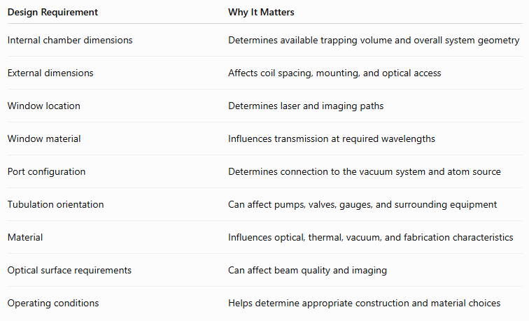
The more information available at the quotation stage, the easier it is to evaluate the design for manufacturability.

A drawing is even better.

We like drawings.

Stock UHV Cells for Related Vacuum Experiments

Not every experiment requires a fully custom MOT chamber.

FireflySci also offers a selection of stock UHV cells that may work for related vacuum, spectroscopy, fluorescence, atomic physics, and experimental applications.

These stock configurations can also provide a useful starting point when determining whether your experiment requires a completely custom MOT cell.

Browse FireflySci UHV Cells:
https://www.fireflysci.com/uhv-cells

If one of our stock cells gets you most of the way there, contact us to discuss whether a custom or modified configuration makes more sense.

Custom MOT Cells From FireflySci

A Magneto-Optical Trap (MOT) Cell has a deceptively difficult job.

It needs to maintain the environment required for atomic trapping while giving lasers, imaging systems, magnetic fields, vacuum hardware, and the rest of your experimental setup room to do their jobs.

That combination makes MOT cells a natural candidate for custom manufacturing.

FireflySci works with researchers who need optical cells beyond ordinary catalog configurations. Our custom manufacturing capabilities cover specialized glass and quartz cells, vacuum-compatible components, fused-silica designs, custom geometries, optical interfaces, and other components built around demanding experimental requirements.

If you already have a drawing for your MOT cell, send it our way.

If you have dimensions, material requirements, vacuum connections, laser wavelengths, and a sketch that looks like it was drawn on the back of a napkin, send that too.

We'll help you determine the next step.

Need a Custom Magneto-Optical Trap (MOT) Cell?

Whether you are building a new cold atom experiment, replacing an existing chamber, or designing something that simply does not exist in a catalog, FireflySci can work with you on a custom Magneto-Optical Trap (MOT) Cell built around your application.

Have your specifications ready? Send us your drawings, dimensions, material requirements, optical requirements, and vacuum interface details for review.

For experiments that may not require a completely custom MOT chamber, be sure to check out our stock UHV cells as well:

https://www.fireflysci.com/uhv-cells

Because when you are trying to control atoms with lasers at microkelvin temperatures, your glass cell should probably be the easy part.

Here's to your success!

FireflySci, Inc.

FireflySci Type 507 Optical Glass Cuvette Used in Nanoparticle Research

Big discoveries can come from studying some very small things.

Researchers from the California Institute of Technology and the Yonsei-Institute for Basic Science's Center for NanoMedicine recently took a closer look at how heat moves away from magnetic nanoparticles. Their research addressed a longstanding question about whether these tiny particles can trap unusually high amounts of heat near their surfaces.

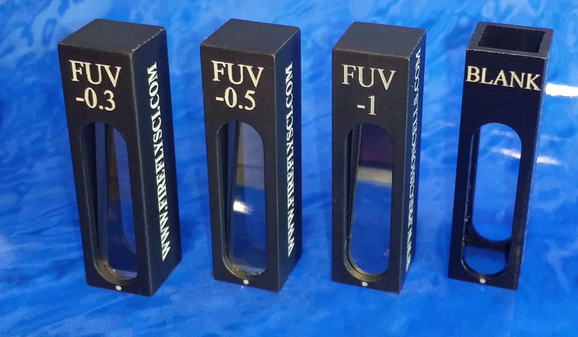
Helping make those measurements possible was an Optical Glass Cuvette from FireflySci.

The team's findings provide a clearer picture of how magnetic nanoparticles behave when exposed to radio frequency alternating magnetic fields, with implications for researchers exploring nanoparticle heating in biology and medicine.

Why Heat Up Nanoparticles?

Iron oxide nanoparticles are extremely small particles with magnetic properties. When certain magnetic nanoparticles are exposed to a radio frequency alternating magnetic field, they can generate heat.

That makes them particularly interesting for biomedical research.

One established application is magnetic nanoparticle hyperthermia, where magnetic nanoparticles are introduced into tissue and remotely heated using an alternating magnetic field. The resulting increase in temperature can be used to destroy diseased cells or make them more sensitive to chemotherapy or radiation therapy.

Researchers are also interested in using magnetic nanoparticles at lower temperatures to influence biological activity rather than destroy cells.

This possibility raised an important question.

Could the heat generated by an individual nanoparticle remain concentrated immediately around that particle?

If so, researchers might eventually be able to heat or activate extremely small biological targets while limiting the amount of heating elsewhere.

There was just one problem. According to classical heat-transfer theory, the amount of heat produced by an individual magnetic nanoparticle should be far too small to create a significant temperature difference between the particle's surface and the liquid surrounding it.

Previous experiments, however, had reported evidence suggesting otherwise.

The Caltech and Yonsei researchers set out to investigate.

Measuring Heat on the Nanoscale

Measuring temperature around something only a few nanometers across is no easy task.

The researchers developed an all-optical approach to compare the temperature directly at the nanoparticle surface with the temperature of the surrounding liquid.

They used two temperature-sensitive fluorescent dyes.

One dye was attached to the surface of the magnetic nanoparticles. A second dye floated freely in the surrounding solution. Because the fluorescence of both dyes changed with temperature, the researchers could use light to independently monitor temperature at the nanoparticle surface and in the surrounding fluid.

Both dyes could also be excited simultaneously using the team's optical system.

Before those fluorescence signals could provide meaningful temperature measurements, however, the researchers needed to know exactly how each dye responded as temperature changed.

That's where a FireflySci Optical Glass Cuvette entered the experiment.

How a FireflySci Optical Glass Cuvette Supported the Research

The research team built a custom temperature-controlled calibration chamber.

The chamber consisted of a copper block with an opening designed to hold a FireflySci Type 507 Optical Glass Cuvette. A thermoelectric plate attached to the system allowed the researchers to control the sample temperature.

The ferrofluid samples inside the Optical Glass Cuvette contained the nanoparticle-bound fluorescent dye and the freely dissolved fluorescent dye.

Researchers then changed the temperature of the sample through a series of controlled temperature points. At each point, they measured the fluorescence produced by both dyes.

This allowed them to create a calibration showing how fluorescence changed with temperature.

The researchers found a strong linear decrease in fluorescence from both dyes as temperature increased. With those calibration curves established, fluorescence could then serve as an optical thermometer during the team's subsequent nanoparticle heating experiments.

In other words, the Optical Glass Cuvette provided the sample chamber used during an important calibration step. It helped the researchers establish the relationship between temperature and fluorescence before investigating what happened when magnetic nanoparticles were exposed to alternating magnetic fields.

What Did the Team Discover?

The results helped settle an important debate.

The researchers tested several different magnetic nanoparticle compositions. During radio frequency magnetic stimulation, the nanoparticles successfully generated heat.

But the team found no measurable difference between the temperature at the nanoparticle surface and the temperature of the surrounding liquid.

They also investigated ferritin, an iron-containing protein that has been proposed for use in magnetic control of biological processes. Under the conditions tested, ferritin did not produce measurable heating either at its surface or in the surrounding solution.

These findings supported classical heat-transfer theory rather than the idea that substantial amounts of heat remain confined to the immediate nanoscale surroundings of these magnetic particles.

So what about previous experiments that appeared to find nanoscale heat confinement?

The researchers investigated that question too.

Small Measurements, Big Potential for Error

At this scale, the way temperature is measured matters.

The team recreated aspects of previous experimental approaches and identified potential sources of measurement artifacts.

For example, comparing an optical measurement at the nanoparticle surface with a physical temperature probe in the surrounding liquid could make it appear that the particle surface was hotter. The physical probe did not respond to temperature changes in exactly the same way as the optical measurement.

By instead using two fluorescent dyes measured simultaneously with the same optical approach, the researchers were able to make a more direct comparison.

That is an important lesson extending beyond this particular experiment.

When scientists are studying changes occurring at extremely small scales, the experimental setup itself can influence what they appear to observe. Careful sample handling, calibration and optical measurement become critical to separating a real phenomenon from a measurement artifact.

Why Optical Glass Cuvettes Matter in Fluorescence Research

A cuvette may be one of the simpler-looking components in a laboratory optical system, but it occupies an important position: directly between the sample and the light being used to study it.

An Optical Glass Cuvette provides a controlled sample chamber through which excitation and emitted light can pass during compatible spectroscopy experiments.

Depending on the application, researchers may also need to consider factors such as optical path length, sample volume, cuvette geometry, wavelength range and instrument compatibility.

In this experiment, the FireflySci Type 507 Optical Glass Cuvette was incorporated directly into a custom-built temperature-controlled holder. This gave the researchers a practical sample chamber for calibrating the fluorescent temperature probes central to their experiment.

The research is also a good example of how a seemingly small laboratory component can support much larger scientific questions.

From Nanoparticles to the Next Experiment

Scientists continue to push experiments into smaller spaces, from nanoparticles and individual cells to microfluidic devices and organ-on-chip platforms.

As experiments shrink, choosing the right sample container becomes increasingly important. Researchers may need smaller sample volumes, specialized geometries or optical access designed around a particular measurement system.

FireflySci manufactures Optical Glass Cuvettes, micro cuvettes, fluorescence cuvettes and other spectroscopy cells for researchers working across a wide range of applications.

Sometimes advancing science means building a massive new instrument.

Other times, it starts with finding the right little cell to hold your sample.

Looking for an Optical Glass Cuvette for your next experiment? Explore FireflySci's spectroscopy cuvettes or contact us for help finding a cell that fits your application.

Learn More

Research Paper: Hunter C. Davis, Sunghwi Kang, Jae-Hyun Lee, Tae-Hyun Shin, Harry Putterman, Jinwoo Cheon, and Mikhail G. Shapiro. Nanoscale Heat Transfer from Magnetic Nanoparticles and Ferritin in an Alternating Magnetic Field. Biophysical Journal, 2020.

When Atoms Start Acting as One: Inside Bose-Einstein Condensates (BEC) and the Cells That Make Them Possible

Most glass cells do not get to participate in creating an entirely different state of matter.

Bose-Einstein Condensate (BEC) cells do.

Inside these specialized vacuum cells, researchers can cool collections of atoms to extraordinarily low temperatures, eventually reaching conditions where something remarkable happens. Instead of behaving like a collection of independent particles, a large number of bosons can occupy the same quantum state, allowing quantum behavior to emerge on a scale researchers can directly study.

Welcome to the wonderfully strange world of the Bose-Einstein condensate.

BEC experiments sit at the intersection of atomic physics, quantum optics, precision measurement, quantum sensing, and fundamental physics. They also place some unusual demands on the glass or quartz chamber at the center of the experiment.

That is where FireflySci comes in.

FireflySci manufactures custom Bose-Einstein Condensate (BEC) cells, MOT cells, UHV cells, and specialized optical cells for researchers whose experiments have officially graduated beyond anything you are likely to find sitting on a laboratory supply shelf.

So, how does a BEC work, why does the cell matter, and what does it take to build one?

Let's get cold.

What Is a Bose-Einstein Condensate?

A Bose-Einstein condensate, or BEC, is a state of matter that can form when a dilute gas of bosonic particles is cooled to extremely low temperatures.

And when we say cold, we mean cold.

Temperatures in BEC experiments can reach the nanokelvin regime, just fractions of a degree above absolute zero.

As the gas becomes colder, the atoms move more slowly. Eventually, their quantum-mechanical wave nature becomes increasingly important. At sufficiently low temperatures and high phase-space density, a large fraction of the atoms can occupy the same lowest-energy quantum state.

At that point, treating every atom as a completely independent particle stops being particularly useful.

The collection begins displaying collective quantum behavior.

That is the magic of a BEC.

It gives researchers an opportunity to investigate quantum-mechanical phenomena using clouds containing thousands, millions, or even more atoms.

who’s the bose?

Bose, Einstein, and a Prediction That Took 70 Years to See

game recognizes game.

The theory behind Bose-Einstein condensation dates back to the 1920s.

Indian physicist Satyendra Nath Bose developed a new statistical treatment of photons. Albert Einstein recognized the importance of Bose's work and extended the underlying statistics to massive particles.

The theory predicted that at sufficiently low temperatures, particles obeying what became known as Bose-Einstein statistics could accumulate in the same quantum state.

There was just one little problem.

Nobody could make a gas cold enough to see it.

That changed in 1995, when Eric Cornell, Carl Wieman, and their team at JILA created the first gaseous Bose-Einstein condensate using rubidium-87 atoms.

The first BEC contained roughly 2,000 atoms and was only about 20 micrometers across.

And where did this new state of matter appear?

Inside a glass cell.

More on that in a minute.

How Do You Make a Bose-Einstein Condensate?

There is no single universal BEC apparatus. Different laboratories use different atomic species, vacuum systems, trap geometries, laser arrangements, and cooling strategies.

But a simplified BEC experiment often follows a progression that looks something like this.

Step 1: Start With an Atomic Gas

Researchers first need a source of atoms.

Rubidium is particularly common in BEC research, although sodium, lithium, potassium, strontium, and other atomic species are also used.

The atoms are introduced into a vacuum system where researchers can begin controlling them without constant collisions with ordinary air molecules.

That brings us to one of the most important ingredients in the experiment.

Vacuum.

A lot of vacuum.

Step 2: Capture the Atoms With a Magneto-Optical Trap

A magneto-optical trap, or MOT, is frequently one of the first major cooling stages in a BEC experiment.

A MOT typically combines red-detuned laser beams with a spatially varying magnetic field. The laser light reduces atomic velocity while the magnetic field helps produce a restoring force that confines atoms around the center of the trap.

The result is a cloud of cold atoms.

Cold, however, is relative.

A MOT can get atoms extraordinarily cold by everyday standards, but creating a BEC usually requires pushing the temperature substantially lower.

Step 3: Transfer the Atoms

Some BEC systems perform multiple stages of the experiment inside one chamber.

Others use separate chambers.

For example, a larger MOT cell may be optimized for capturing a substantial number of atoms. Those atoms can then be transferred through the vacuum system into a smaller science cell, where the final cooling stages and experiments occur.

This separation allows researchers to optimize different parts of the vacuum system for different jobs.

The MOT wants lots of atoms.

The science chamber wants exceptionally clean vacuum conditions, strong optical access, and precise control.

Getting both simultaneously can be tricky.

Step 4: Keep Cooling

After initial laser cooling, atoms can be transferred into magnetic or optical traps for further cooling.

One widely used technique is evaporative cooling.

The concept is somewhat similar to cooling a cup of coffee through evaporation. The highest-energy atoms are selectively allowed to escape the trap. The remaining atoms collide and redistribute their energy, lowering the temperature of the sample.

Repeat the process, and the remaining cloud becomes progressively colder.

Eventually, the system can cross the threshold into Bose-Einstein condensation.

Step 5: A BEC Appears

As the temperature falls and the phase-space density increases, a significant fraction of the bosonic atoms can begin occupying the same quantum state.

The result is the BEC.

Researchers can then manipulate, release, image, split, interfere, transport, or otherwise experiment with the condensate.

Which is where things get really interesting.

What Is a Bose-Einstein Condensate Cell?

A BEC cell is the optical vacuum chamber where some or all of the cooling, trapping, condensation, manipulation, and imaging stages of a Bose-Einstein condensate experiment take place.

Depending on the apparatus, you might also hear terms such as:

  • BEC vacuum cell

  • BEC science cell

  • BEC-MOT cell

  • Ultracold atom cell

  • Cold atom vacuum cell

  • Quantum optics cell

  • UHV glass cell

  • MOT-BEC chamber

The exact design can vary dramatically.

Some BEC cells are relatively simple rectangular glass chambers. Others use multiple windows, specialized tubes, graded seals, CF flange connections, octagonal geometries, or other custom configurations.

There is a reason for all that customization.

The cell is not merely a container.

It is part vacuum chamber, part optical component, and part interface between a collection of highly specialized experimental systems.

Why Does a BEC Cell Need Ultra-High Vacuum?

If you are trying to maintain a delicate cloud of ultracold atoms, random collisions are not your friend.

Atoms and molecules from the surrounding environment can collide with trapped atoms, transferring energy and ejecting them from the trap.

That means BEC experiments typically need extremely low background pressures.

Depending on the experiment, pressures in the science region can reach the 10⁻¹⁰ to 10⁻¹¹ Torr range or lower.

At these pressures, collisions with background gas become infrequent enough to provide the trap lifetimes needed for cooling and experimentation.

The glass cell therefore has to become an integral part of an ultra-high-vacuum system.

That affects practically everything about its design, including material selection, seals, connections, surface cleanliness, manufacturing processes, geometry, and how the finished cell connects to the rest of the vacuum apparatus.

FireflySci already specializes in optical cells built for demanding vacuum environments.

Our stock UHV cells provide examples of quartz-to-Pyrex and metal-to-Pyrex graded-seal constructions designed for high-vacuum applications.

You can explore them here:

https://www.fireflysci.com/uhv-cells

For BEC research, however, the required geometry can quickly become much more specialized.

That is where custom manufacturing enters the picture.

Optical Access: When Your Vacuum Chamber Also Needs to Be an Optical Component

Creating the vacuum is only half the battle.

Researchers also need to get light into and out of the chamber.

A lot of it.

A BEC experiment can involve MOT beams, imaging beams, optical pumping beams, dipole-trap beams, push beams, repump beams, probing light, and other optical pathways.

Suddenly that little glass box is surrounded by an impressive amount of equipment.

The optical surfaces of the BEC cell therefore matter.

Depending on the experiment, researchers may need to consider:

  • Window flatness

  • Parallelism

  • Surface quality

  • Optical transmission

  • Laser wavelength

  • Reflections

  • Beam distortion

  • Scattering

  • Window dimensions

  • Optical path position

  • Imaging geometry

  • Working distance

  • Distance between the atoms and cell wall

This is also why rectangular, square, octagonal, and other multi-window geometries can be attractive for cold atom research.

The goal is not simply to see inside the chamber.

The goal is to interact with the atoms inside it from precisely the right directions.

A BEC Cell Can Be Very Different From a MOT Cell

MOT and BEC cells are closely related, but the terms should not always be treated as interchangeable.

A MOT cell is primarily associated with the magneto-optical trapping stage.

A BEC science cell may be optimized for later stages of the experiment, including evaporative cooling, optical or magnetic trapping, manipulation, and imaging of the condensate.

Some systems combine these functions into a single chamber.

Others separate them.

One example comes from the Bose-Einstein Condensation Lab at the University of Arizona. Its experimental system has used two glass cells. A larger MOT cell was used to laser-cool more than one billion rubidium atoms, while a smaller science cell was used for the evaporation stage that produced the BEC and for subsequent interaction with imaging beams and other experimental parameters.

The atoms were magnetically transported between the two regions.

This demonstrates why calling FireflySci with nothing more than "I need a BEC cell" might be the beginning of the conversation rather than the end.

We need to know what the cell is actually going to do.

BEC Cell Materials: Borosilicate, Quartz, and Fused Silica

Material selection depends on the requirements of the experiment.

Borosilicate Glass

Borosilicate materials can provide a useful combination of fabrication flexibility, optical performance, and thermal properties.

They can be particularly useful when a design requires glassblown components, tubulations, vacuum connections, or transitions to other materials.

Fused Silica and Quartz

Fused silica may be desirable when researchers require excellent optical properties, UV transmission, low thermal expansion, or specialized optical performance.

FireflySci has extensive experience manufacturing precision optical cells from quartz and fused silica, along with borosilicate and graded-seal constructions.

For a custom BEC cell, material selection should be driven by the actual experiment.

The questions we want to know include:

What wavelengths are you using?

What vacuum level are you targeting?

Does the system need to be baked?

What flange or vacuum connection is required?

How close do your atoms need to be to a particular window?

What imaging resolution are you trying to achieve?

How much physical space is available between coils?

Once those questions start getting answered, the correct cell begins taking shape.

BEC Experiments That Show Just How Important the Cell Can Be

Bose-Einstein condensation has gone from an exotic laboratory achievement to an experimental platform used throughout modern atomic physics.

And glass cells have been along for quite a bit of that journey.

The First Bose-Einstein Condensate

On June 5, 1995, the JILA team led by Eric Cornell and Carl Wieman produced the first gaseous Bose-Einstein condensate.

The team used laser and magnetic traps to cool rubidium atoms until roughly 2,000 atoms formed a condensate.

The BEC was created inside a carrot-sized glass cell surrounded by lasers, magnets, and laboratory equipment.

That tiny cloud helped open an entirely new area of experimental atomic physics.

Not bad for a day's work inside a glass cell.

Two Glass Cells for Rubidium BEC Research

The University of Arizona's Bose-Einstein Condensation Lab provides another great example of why custom cell geometry matters.

Its apparatus has used a larger glass MOT cell to capture and initially cool rubidium atoms, followed by magnetic transport into a smaller glass science cell.

The science cell operates at extremely low pressure and provides the environment where evaporative cooling and subsequent BEC experimentation can occur.

This type of architecture highlights an important point: sometimes the ideal BEC apparatus is not one cell.

It is an interconnected vacuum system containing multiple cells optimized for different stages of the experiment.

Creating BECs in Space

Then somebody decided Earth was making things too easy.

NASA's Cold Atom Laboratory (CAL) launched to the International Space Station in 2018 and became the first facility to create Bose-Einstein condensates in Earth orbit.

Why take BEC research to space?

Gravity.

On Earth, gravity affects how an ultracold atomic cloud expands and evolves after its trap is weakened or released. In microgravity, researchers can investigate the condensate over longer free-evolution times and under conditions difficult to reproduce in terrestrial laboratories.

The Cold Atom Lab has worked with ultracold rubidium and potassium atoms and is operated remotely from NASA's Jet Propulsion Laboratory.

The science module brings the vacuum system, lasers, magnetic trapping hardware, electronics, and other equipment needed for ultracold atom research into an extraordinarily compact package.

It is a spectacular example of how far BEC experiments have come since 1995.

From a tabletop glass cell to orbit in a little over two decades.

Continuous Bose-Einstein Condensation

BEC research continues to evolve.

Researchers have also demonstrated continuous Bose-Einstein condensation, rather than treating BEC creation solely as a repeated batch process.

One experimental approach using strontium continuously feeds laser-cooled atoms from a steady-state MOT into a reservoir and a deeper "dimple" trap. Cooling, replenishment, and condensation can then occur continuously.

Experiments like this illustrate how sophisticated cold atom systems are becoming and why the vacuum chamber must be considered as part of a complete optical and mechanical system rather than an isolated component.

What Can FireflySci Customize on a BEC Cell?

This is the fun part.

BEC experiments tend to be highly specialized, which means a stock vacuum cell may be perfect for one laboratory and completely useless for the one next door.

FireflySci can manufacture custom BEC cells and related UHV optical cells around the requirements of the experiment.

Depending on manufacturing feasibility, customization can include:

  • Cell length, width, and height

  • Rectangular or specialized chamber geometries

  • Optical window dimensions

  • Optical window locations

  • Wall thickness

  • Quartz or glass material selection

  • Tubulations

  • Vacuum connections

  • Graded seals

  • Metal-to-glass transitions

  • CF flange integration

  • Custom optical paths

  • Specialized window arrangements

  • Designs based on customer drawings

  • Modifications based on existing cell geometries

The most important word here is custom.

A BEC cell should be designed around the optical table, coils, vacuum system, laser geometry, imaging system, and experiment it is going into.

Not the other way around.

What Should You Consider When Designing a Custom BEC Cell?

If you are preparing a drawing or RFQ for a custom Bose-Einstein Condensate cell, more information is almost always better.

SpecificationWhy It MattersCell geometryDetermines optical access and integration with the experimentInternal dimensionsDefines usable experimental volumeExternal dimensionsAffects coil spacing and surrounding hardwareMaterialInfluences optical, thermal, and fabrication propertiesLaser wavelengthsHelps determine optical material requirementsWindow locationsDetermines beam and imaging accessDistance to atom cloudCan be critical for imaging and field generationVacuum levelInfluences construction and connection requirementsVacuum connectionDetermines integration with pumps and other chambersBakeout requirementsCan affect material and joining choicesTubulationsConnect atom sources and vacuum componentsOptical requirementsHelps define surfaces, transmission, and coatingsMechanical restrictionsEnsures the finished cell actually fits into the apparatus

And please send a drawing whenever possible.

CAD drawings are fantastic.

Dimensioned sketches are fantastic.

A carefully labeled napkin drawing can still tell us quite a bit.

Why Put the Atoms Close to the Glass?

Another design consideration in some BEC experiments is the distance between the trapped atoms and the cell wall.

Smaller science cells can allow magnetic coils, atom chips, objectives, and other experimental hardware to sit closer to the atomic cloud.

That can matter for generating strong magnetic-field gradients or achieving high-resolution imaging.

But making a chamber smaller also introduces tradeoffs.

Researchers still need adequate optical access, vacuum conductance, mechanical strength, manufacturing tolerances, and room for whatever beams need to pass through the experiment.

This is exactly why BEC cell design becomes an exercise in balancing requirements rather than simply picking a chamber size.

BEC Cells and Atom Chips

Some modern BEC experiments combine ultra-high-vacuum glass cells with atom chips.

These systems use microfabricated conductors and structures to generate highly localized magnetic or electromagnetic potentials near the atomic cloud.

Rubidium BEC experiments have, for example, loaded laser-cooled atoms into an ultra-high-vacuum glass science cell containing an atom chip, initially capturing the atoms with a MOT before transferring them into magnetic microtraps and using evaporative cooling to reach quantum degeneracy.

For these systems, chamber geometry becomes especially important because researchers may need to balance optical access with extremely short distances between the atoms and chip surface.

Once again, the humble glass cell is doing considerably more work than its appearance suggests.

What Are Bose-Einstein Condensates Used to Study?

Creating a BEC is impressive.

But for most research groups, creating it is only the beginning.

BECs have become experimental tools for investigating subjects including:

  • Quantum mechanics

  • Matter-wave interference

  • Atom interferometry

  • Superfluidity

  • Quantum simulation

  • Quantum sensing

  • Precision measurement

  • Atom optics

  • Atomic interactions

  • Quantum phase transitions

  • Optical lattices

  • Many-body physics

  • Fundamental tests of physics

Researchers have also developed atom lasers, where coherent matter waves are extracted from a BEC in a concept loosely analogous to extracting coherent light from an optical laser.

And as the Cold Atom Laboratory demonstrates, ultracold atom research is increasingly being investigated for precision sensing and space-based quantum experiments.

A tiny cloud of extremely cold atoms can make a surprisingly capable laboratory.

Why Glass Cell Geometry Matters So Much

There is a recurring theme in BEC apparatus design:

Everything wants to occupy the same space.

The lasers need optical access.

The magnetic coils need to get close to the atoms.

The imaging objective wants a clear view.

The vacuum connection has to go somewhere.

The atom source needs access.

The pump needs adequate conductance.

The optical table is already full.

And the atoms, naturally, need to end up exactly where everything intersects.

This is why custom BEC cells can range from simple rectangular chambers to multi-window and multi-port designs.

A few millimeters in the wrong direction can interfere with a coil, clip a laser beam, restrict an imaging path, or make mounting unnecessarily difficult.

Custom manufacturing lets the chamber become part of the apparatus design from the beginning.

Looking for Something Simpler? Start With FireflySci UHV Cells

Not every cold atom or vacuum experiment requires a completely custom chamber.

FireflySci also offers stock UHV cells designed for experiments requiring specialized high-vacuum optical access.

Our available configurations include quartz-to-Pyrex and metal-to-Pyrex graded-seal designs in multiple optical path configurations.

You can explore our stock options here:

https://www.fireflysci.com/uhv-cells

These cells may work directly for certain vacuum experiments or provide a useful starting point when discussing a more specialized configuration.

If your requirements go beyond our catalog, that is when we start talking custom.

Custom Bose-Einstein Condensate (BEC) Cells From FireflySci

A Bose-Einstein Condensate cell may look simple sitting by itself.

Put it into an actual experiment and the picture changes quickly.

Now it has to maintain ultra-high vacuum while providing precisely positioned optical access for lasers and imaging systems. It may need to sit between magnetic coils, connect to pumps and atom sources, accommodate unusual wavelengths, withstand vacuum processing, and fit into a laboratory setup where every millimeter has already been claimed by something else.

That is exactly the type of challenge custom scientific glass manufacturing is built for.

FireflySci has extensive experience manufacturing precision quartz, fused silica, borosilicate, graded-seal, vacuum, cryogenic, and custom optical cells for demanding research applications.

Whether you need a relatively straightforward rectangular science cell or a completely custom BEC-MOT chamber designed around an existing experimental setup, send us the specifications.

Dimensions help.

Materials help.

Laser wavelengths help.

Vacuum requirements help.

Drawings really help.

We'll work with you to determine how the cell can be manufactured around the needs of your experiment.

Ready to Build Your BEC Experiment?

When you're trying to persuade thousands of atoms to stop acting like individuals and start behaving as a single quantum system, there are already enough variables to worry about.

Your cell does not need to be another one.

Send FireflySci your drawings and requirements for a custom Bose-Einstein Condensate (BEC) cell, MOT-BEC cell, science cell, or related UHV optical chamber.

Or, if your experiment can work with an existing configuration, take a look at our stock UHV cells here:

https://www.fireflysci.com/uhv-cells

From the first rubidium condensate in a small glass chamber to BEC experiments orbiting hundreds of kilometers above Earth, one thing is clear.

Sometimes very big physics happens inside a surprisingly small piece of glass.

Here's to your success!

FireflySci, Inc.

Microfluidic Devices: Advancing Precision in Fluid Dynamics

Microfluidic devices manipulate incredibly small volumes of fluids within micro-scale channels, enabling a level of precision and efficiency that is reshaping scientific research, diagnostics, and industrial applications. Often referred to as lab-on-a-chip systems, these platforms condense complex laboratory procedures into compact, automated devices, providing faster results, greater reproducibility, and reduced operational costs.

At the forefront of this field are microfluidic chips from FireflySci, meticulously engineered for consistent performance, scalability, and user-friendly integration into diverse experimental setups.

A Brief History: From Early Concepts to Modern Microfabrication

The development of microfluidics can be traced back to innovations in microelectronics and inkjet printing in the 1950s, which demonstrated the feasibility of manipulating fluids at extremely small scales. The late 1970s saw the creation of the first silicon-based miniaturized gas chromatographs, sparking interest in compact fluid control systems. By the 1980s, Micro-Electro-Mechanical Systems (MEMS) emerged, bridging electronics and microfluidics and setting the stage for high-precision fluid handling.

A pivotal moment came in the late 1990s with the advent of soft lithography using PDMS, pioneered at Harvard, which dramatically lowered the barriers to microfluidic device fabrication. This technology allowed for rapid prototyping and opened the field to a broader range of applications and researchers.

Why Microfluidics Matter

Microfluidic devices offer advantages that traditional laboratory systems cannot match:

  • Minimal Sample Requirements: Operations can be performed using nanoliter or even picoliter volumes, significantly reducing reagent use and costs.

  • Rapid Processing: Short diffusion distances accelerate chemical reactions and biological assays.

  • Enhanced Precision: Micro-scale control over fluid flow, temperature, and chemical gradients ensures reproducibility.

  • Automation and Integration: On-chip control systems minimize human error and streamline complex workflows.

  • Portability: Compact designs enable field diagnostics, environmental testing, and remote analysis.

Key Applications Across Fields

Microfluidic devices are making a profound impact across multiple sectors. In point-of-care diagnostics, they enable rapid detection of infectious diseases in both urban hospitals and remote locations, reducing diagnostic time from days to minutes. For single-cell genomics, microfluidics allow scientists to study individual cells in isolation, revolutionizing cancer research, immunology, and regenerative medicine.

In drug discovery and development, high-throughput screening on microfluidic platforms allows simultaneous testing of thousands of compounds, expediting pharmaceutical pipelines. Environmental monitoring benefits from real-time detection of pollutants, heavy metals, and pathogens in water sources, enhancing public health protection. The food industry relies on these devices for rapid identification of contaminants, improving safety and compliance.

Advanced chemical synthesis in micro-reactors enables precise control of reaction parameters, fostering innovation in material science. Biomedical research is leveraging organ-on-a-chip technology to model human organs for drug testing and disease modeling, reducing reliance on animal testing. In the emerging field of space bioscience, microfluidics provide a means to study biological processes in microgravity, aiding long-duration space exploration.

Choosing the Right Platform

Material selection influences performance and suitability for different applications:

  • PDMS: Transparent, flexible, ideal for prototyping and biological studies.

  • Glass or Silicon: High durability and chemical resistance for industrial or analytical chemistry applications.

  • Plastics: Affordable, disposable options suitable for large-scale diagnostic deployment.

FireflySci: Precision-Engineered Microfluidic Chips

FireflySci’s microfluidic chips blend advanced microfabrication techniques with practical usability. Designed to meet the rigorous demands of academic, clinical, and industrial users, these chips maintain consistent performance in even the most challenging conditions.

With compact, accurate, and reliable microfluidic devices, FireflySci empowers groundbreaking research, faster diagnostics, and innovative industrial solutions—pushing the boundaries of what’s possible in fluid dynamics.